
XDE is an independent physics engine designed to simulate realistic physical behavior and extend or replace the standard physics system traditionally used in real-time applications. Integrated into Skyreal as a dedicated plugin, XDE enables users to create, configure, and interact with physically accurate simulations directly within a Skyreal scene.
This documentation explains how to use the XDE plugin and how to set up a scene in Skyreal in order to achieve realistic physics behavior, from basic configuration to the preparation of objects and simulation parameters.
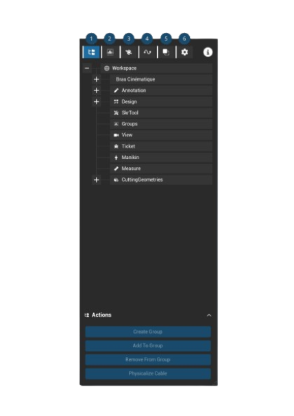
First, launch the Workbench and review the main steps required to set up the simulation. You will see this window.
Step 1 : Define the parts to physicalize
For this part, you should go in the Menu 2-3
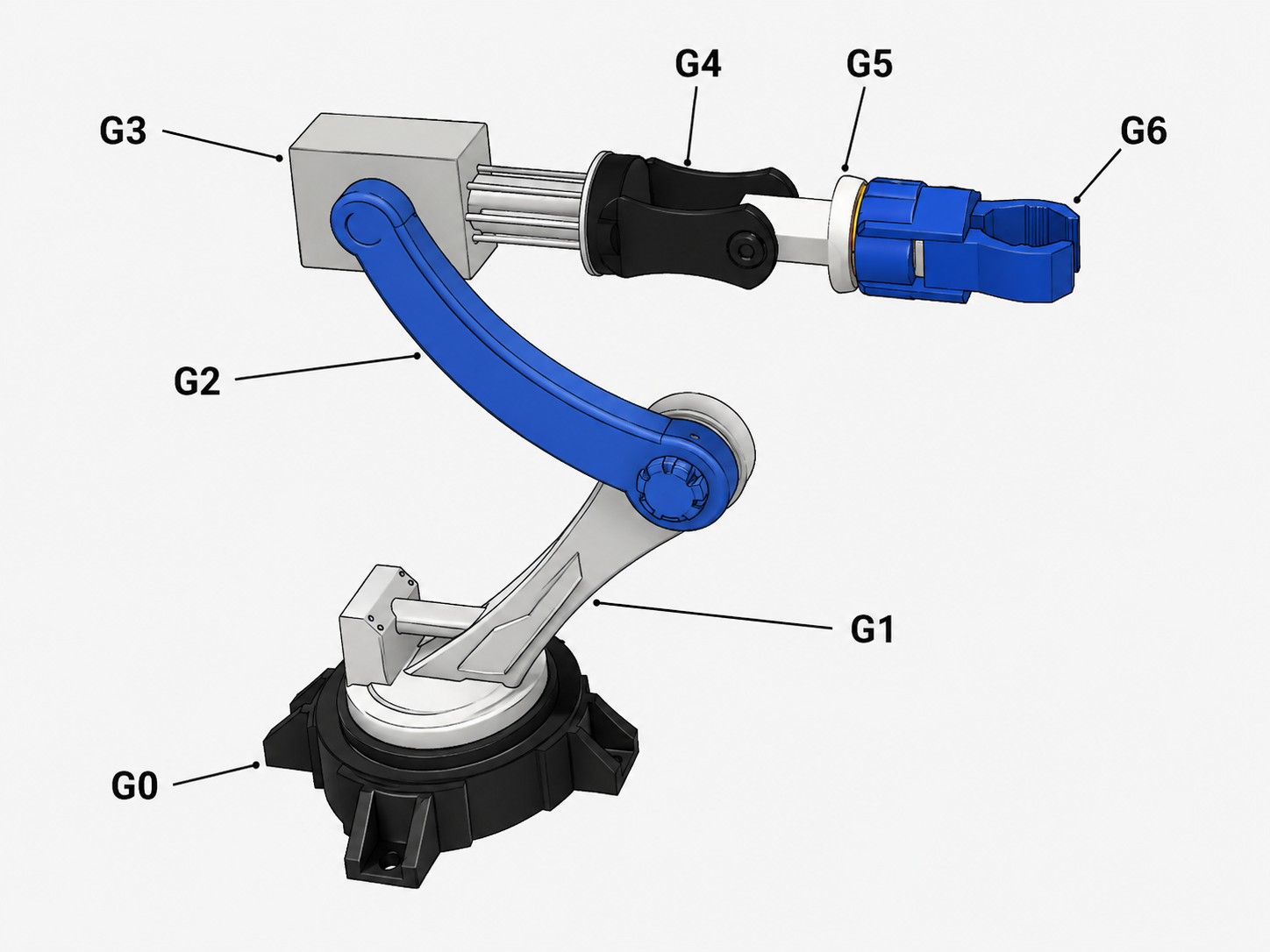
XDE is based on traditional kinematic principles. The first step is therefore to define the groups of parts that need to be physicalized. These groups will then be linked together so they can be animated and simulated as part of a realistic physical system.
To create a group, select all the parts that belong to it. Once the selection is complete, click Create Group.
A new group should then appear in the Groups list. Rename it to provide more context and make it easier to identify. The overlay around the part is now displayed in green, indicating that this group of parts will be physicalized as a single rigid body.
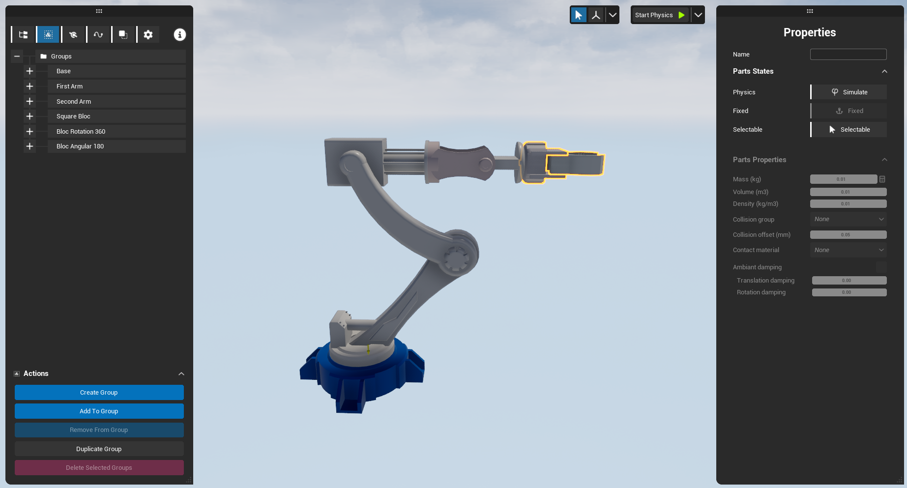
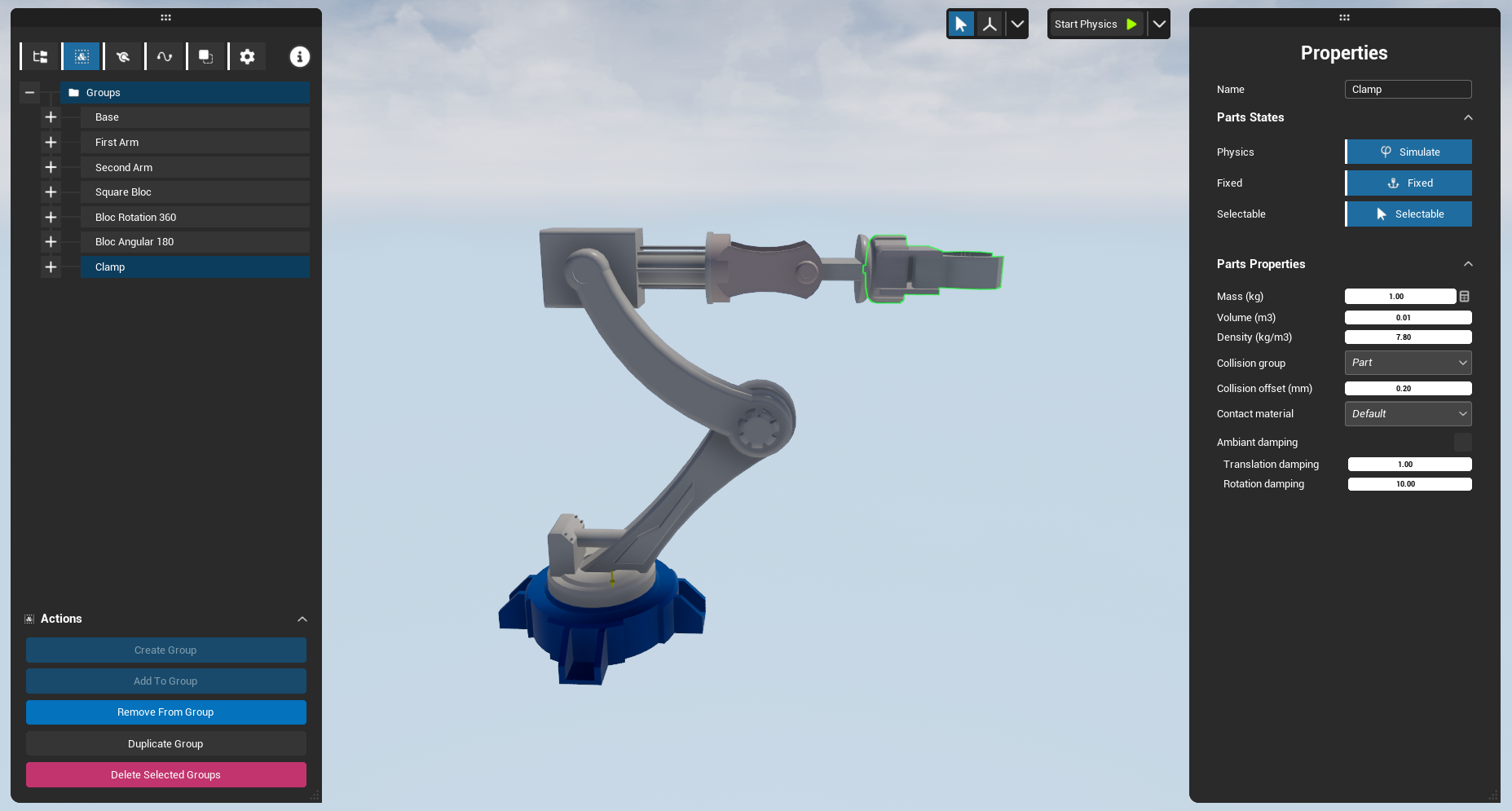
In the Properties window, you can configure several options for the selected group.
Parts States
-
Physics : Defines whether the group will be physicalized or not.
-
Fixed : Defines whether the group is fixed or movable. This is generally used for static structures or frames.
-
Selectable : Defines whether the group can be selected or grabbed by the user. This is useful to prevent users from grabbing parts that should remain fixed.
Parts Properties
(these parameters influence the physical simulation calculations.)
-
Mass (kg) : Defines the mass of the group.
-
Volume (m³) : Defines the volume of the group.
-
Density (kg/m³) : Defines the density of the group.
-
Collision group :
Defines the type of collision applied to the group.
-
Part : The group collides with any other physical object.
-
Attach : The group behaves as a physical part but does not collide with cables.
-
Cable : The group is treated as a cable physics element.
-
Off : The group has no collision.
-
-
Collision offset (mm) : Defines the distance at which two groups are considered to be in collision.
-
Translation Damping : Defines the damping applied to linear movements.
-
Rotation Damping : Defines the damping applied to rotational movements. :
Step 2 : Implement the constraints
For this part, you should go in the Menu 3
Once the physical groups have been defined, the next step is to create the mechanical constraints between them. To do so, click Create New Constraint and select the type of constraint you want to add from the following list:
-
Ball
-
Cardan
-
Cylindrical
-
Fixed
-
Helical
-
Hinge
-
Planar
-
Point on Line
-
Prismatic
-
Serial Hinge 2
-
Serial Hinge 3
-
Snake
After creating the constraint, click the Parent and Child targets to define which physicalized groups are involved in the connection. A green overlay will appear, allowing you to select the corresponding part directly in the scene.
Please note that a part must be physicalized before it can be used in a constraint. Non-physicalized parts cannot be selected as constraint bodies.
In most cases, four parameters are common to all constraint types:
Dans la grande majorité des cas il y a quatre éléments qui sont communs à chaque liaison :
-
Inhibit Body Collision : Disables collisions between the two bodies connected by the constraint.
-
Model : Defines the constraint model used by XDE. Reduced is the standard model, while Compliant is generally used for freeze constraints outside of grab interactions.
-
Damping : Applies fluid friction forces to reduce the forces computed by the system and stabilize the motion.
-
Dry Friction : Applies dry friction forces to reduce the computed forces using a threshold-based behavior.
-
The remaining parameters depend on the selected constraint type. They usually define the specific limits of the constraint, such as maximum translation limits, maximum rotation limits, axis configuration, or other constraint-specific properties.
Once the constraint has been configured, click Place Constraint to position it in the scene. This step defines the constraint reference frame, such as the translation axis, rotation axis, support point, or contact reference, depending on the selected constraint type.
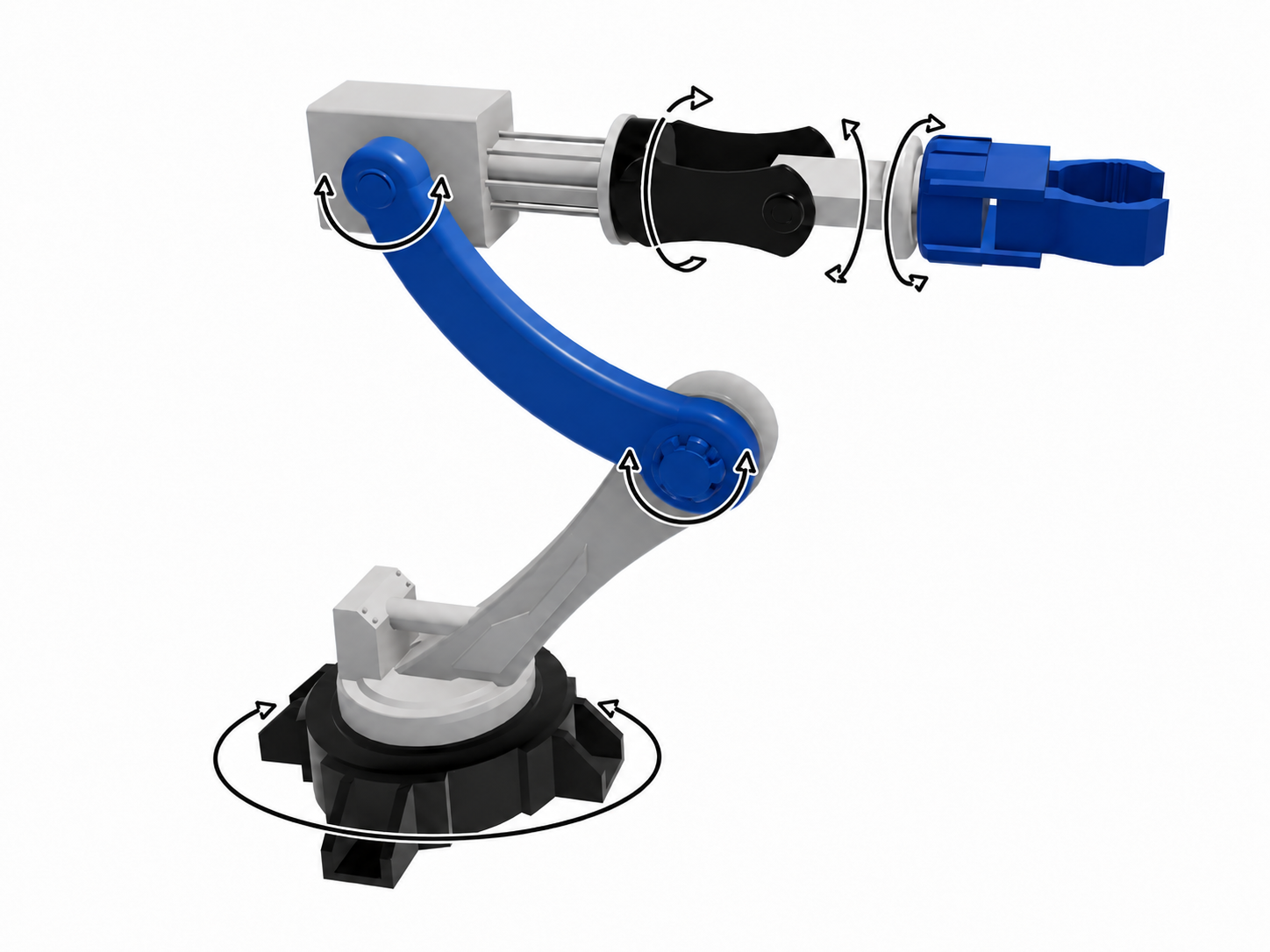
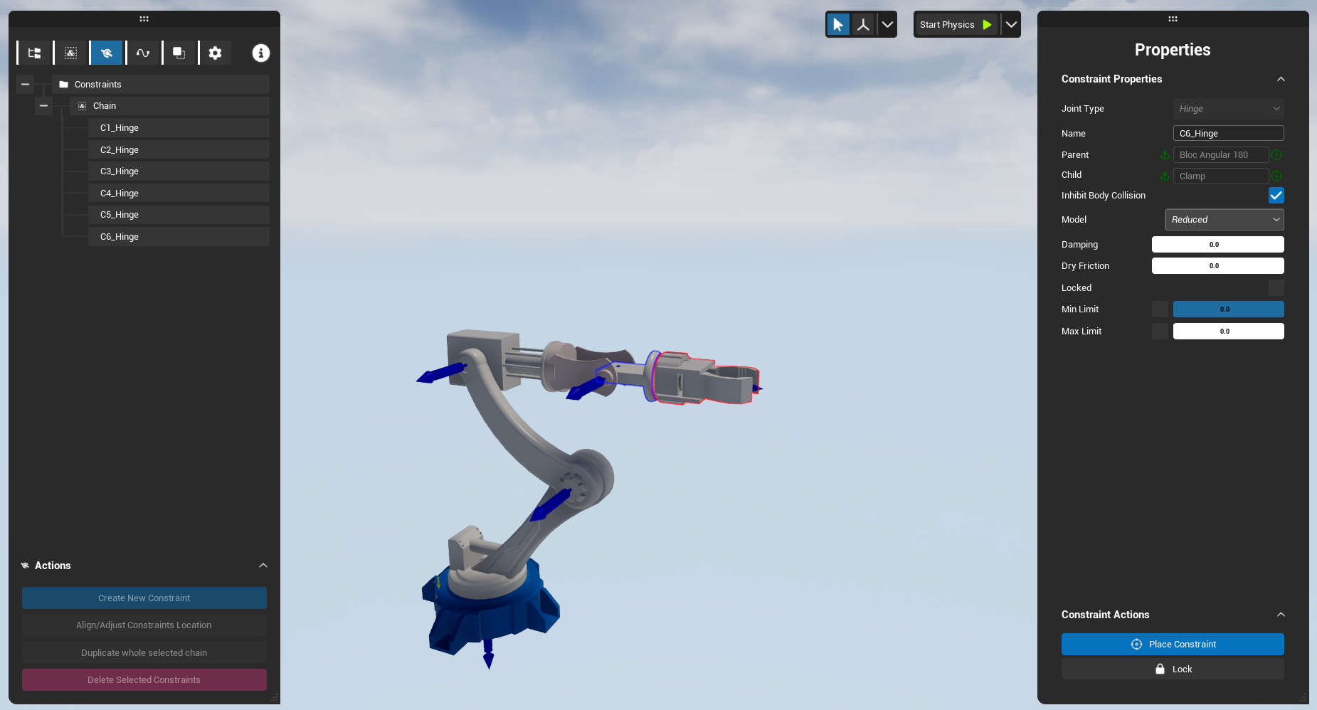
Step 3: Test the physics simulation
After completing the first two steps, you can already test whether the physical behavior works as expected.
To start the simulation, click Start Physics. Depending on your use case, you can enable or disable gravity and collision constraints if they are not required for your study. To access these options, expand the Start Physics button. The gravity and collision settings are available from this menu.
Once physics is enabled, you can activate Physics Grab.
Physics Grab allows you to manipulate physicalized parts while respecting the constraints defined in the Workbench. It is important to note that the grab interaction takes the grabbing position into account when computing the resulting motion. For example, pushing a door from its edge or from its center will not produce the same behavior.
There are two main types of grab:
-
Laser : Grabs the first object hit by the laser. This can be used once per controller.
-
Overlap : Grabs the first object touched by the controller.
-
Incoming Hand Tracking : Hand tracking support is planned for future interaction workflows.
Vous pouvez régler plusieurs paramètres pour régler la force attribuée à votre saisie notamment
Step 4: Physicalizing Cables
To do this, you first need to create a cable directly in Skyreal’s VR mode.
By going directly to Edit Cable, you can add your cables and define the associated constraints.
First, you need to select the elements that will define the cable’s start point and end point. In our example, these are Square Part and Base.
Once both elements have been selected, you can draw the cable using the pencil tool, which replaces your controller.
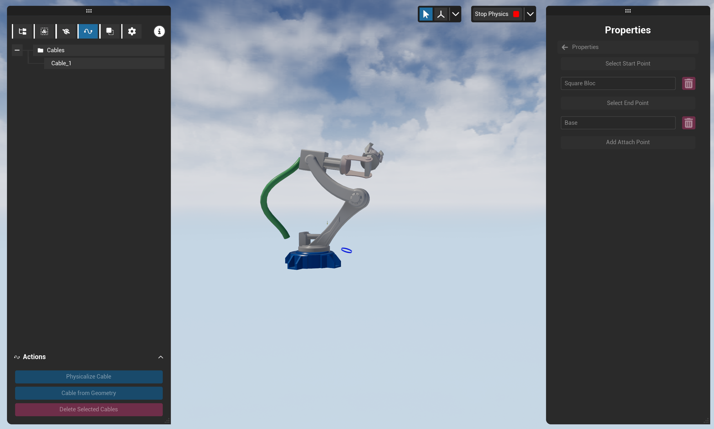
Afterwards, you can modify several parameters in Menu 4.
In General, you can adjust:
-
the radial length;
-
the cable length;
-
the cable density.
In Add Attach Point, the two main attachment points are already selected and can be modified.
You can also add additional attachment points to define a more precise cable path.
In Properties, you can adjust:
-
Young’s modulus;
-
density;
-
the collision group, which should initially be set to Cable.
In the future, it will be possible to select an existing cable and make it physical directly. However, in the current version, it is recommended to recreate a similar cable instead.
Cables have their own physics behavior and are handled differently from other physicalized elements. They can notably be identified by the absence of collision arrows.
Step 5 : Create Snap Points
For this part, you should go in the Menu 5
Creating snap points is particularly useful for assembly or attachment processes. The idea is to create a contact point between two parts so that they automatically connect when they come close enough to each other.
This can be used, for example, for inter-wagon connectors, magnetic elements, harnesses, or any system where two parts need to be assembled or attached together.
In a similar way to constraints, you first need to select the parts that will be linked together before placing their contact point.
Once the snap point has been placed using Place Snap, a yellow circle appears to indicate the attachment point.
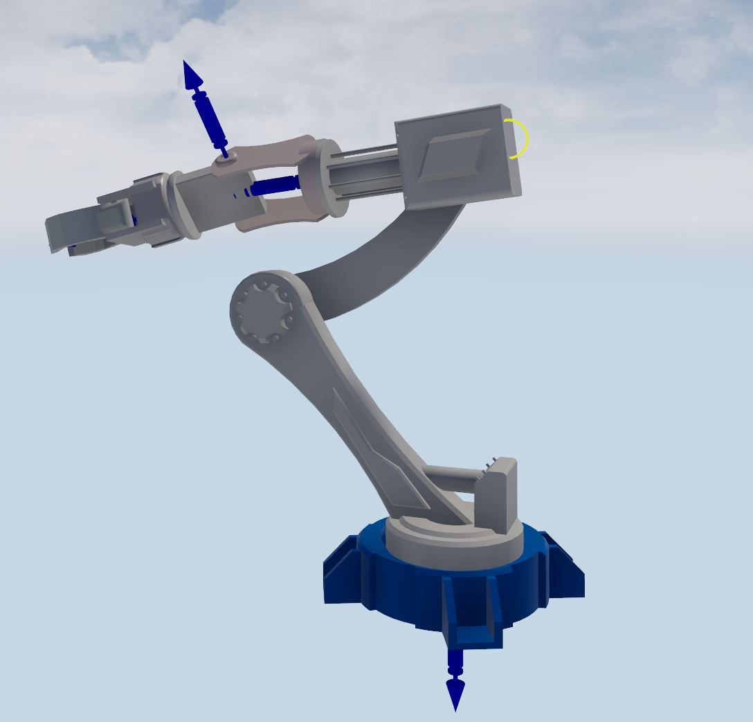
Il ne reste plus qu'à régler les paramètres disponibles dans Properties
-
Snapping Threshold : Defines the distance between the part and its snapping location that triggers the snapping behavior.
-
Rotation Threshold : Enables rotation validation before triggering the snap.
-
Is triggered at Start : Defines whether the part should already be placed at its snapped location when physics starts. This is useful when the part starts in its assembled position and needs to be declared as already snapped.
-
Breakable :Defines whether the user can detach and reattach the part from or to the snap point. If set to false, the part cannot be detached.
Step 6: Best Practices
-
Remember to save your map before starting the physics simulation. This makes it much easier to return to your initial setup if needed with Load last save.
-
Avoid sudden or violent contacts between two objects. The physics simulation runs in real time, and high-speed impacts require significantly more computing resources.
-
When physicalizing your model, try to include as many objects as possible within the same group when relevant. For example, you can create a group, hide it, and then access hidden parts in order to add them to the group afterwards. This is often useful for reaching screws, pins, joints, or other small internal elements.
-
Reducing gravity can also help improve the stability and efficiency of the simulation.